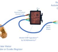
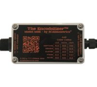
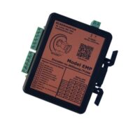
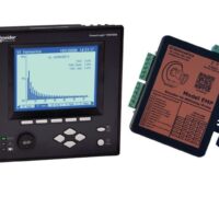
4-20mA Analog Flow-Proportional Outputs Using The EtherMeter

November 3rd, 2011

In most cases, EtherMeter users will collect flow rate data via the device’s digital Ethernet and Serial communication channels.  Digital communication protocols include MODBUS (TCP/RTU/ASCII), DF1, and EtherNet/IP™.

However, in some instances, the user may wish to interface to 4-20mA analog signals that are proportional to flow.  Replacement of Sensus ACK-PAK instrumentation is just one possible use.  However, in this case, the EtherMeter is capable of deriving the 4-20mA signal from either an encoder-type or a pulse-output-type flow meter.  Within the Setup Menu, the EtherMeter also permits the user to specify the 4-20mA span (the flow-rate that corresponds to 20mA).

When used with an encoder-type flow meter, it is important to recognize the limitations of this type of 4-20mA signal.  Because it is not based upon a hard real-time flow-rate signal, the user should therefore exercise caution when using the 4-20mA signal to drive a PID control loop.

SCADAmetrics Analog Flow-Output Demonstrator Panel

This document describes the wiring procedures and EtherMeter settings that are required for 4-20mA output signaling.  Note that the EtherMeter requires Special Firmware plus an ADAM-4024 module (by Advantech) for this option, and so the purchaser must ensure that the Analog-Output Firmware+Module option is selected when buying at the eStore.  Also, it is important to note that when using this option, the ADAM-4024 module consumes the serial port; and therefore any digital communications to the EtherMeter must occur via the Ethernet port.

Detailed procedures are available in a new Application Note posted in the SCADAmetrics Documentation Center:

Link to App Note


Using The Sensus High-Speed Pickup Register (Pulse) With The EtherMeter

October 6th, 2011

In addition to its ability to read most encoder-type flow meters, the EtherMeter also features pulse-input support.

Sensus High-Speed Pickup

The following Application Note details the procedures for connecting a Sensus High-Speed Pickup (Pulse) Register to an EtherMeter; and it also describes an example of modified Setup Menu parameters for the High-Speed Pickup:

http://scadametrics.com/PDF/App_Note_014.pdf

Note that the Sensus High-Speed Pickup requires an external +12VDC power supply.  In this application, we recommend using a single +12VDC power supply to power BOTH the EtherMeter and High-Speed Pickup.

Using EtherMeter Analog Inputs For Temperature Monitoring.

November 8th, 2010

A new application note has been posted to scadametrics.com that describes how to set up one of the EtherMeter’s analog input channels to collect temperature data from a thermistor:

http://scadametrics.com/PDF/App_Note_011.pdf

This type of application could be particularly useful in building automation and industrial control applications where full use of the EtherMeter’s auxiliary I/O channels could potentially save the integrator from the necessity of adding a full-featured controller.

Each EtherMeter contains 2 meter input channels (Each provides totalization and flow-rate), 2 analog input channels (4-20mA or 0-5V), and 3 digital I/O channels.

Thermistor Demonstration Panel. AIN1 = 52.13%, Which Corresponds To 9183 Ohms (Thermistor) And 80.5 degF.

Custody Transfer Meter Sharing Between A Bulk Water Buyer And Seller

October 25th, 2010

Recently, an interesting project was completed at the water custody-transfer point between Williamsville (IL) and Springfield (IL), where Williamsville purchases bulk water from Springfield and transmits it through a system of water towers, pumping stations, and distribution mains.

Williamsville (IL) Pumping Station. Station features a Ground Storage Tank and Altitude Valve, a Master Meter, 2 Pumps, and a Bypass Valve. Williamsville's station is run by an intelligent RTU connected to their Radio SCADA system. Springfield, the bulk seller, monitors the master meter using an Itron radio AMR system.

In the scope of this project, Williamsville installed EtherMeters into their existing distribution SCADA system for the purpose of automated report generation, flow monitoring, and leak detection. 

The custody-transfer master meter was a Badger 6 Inch T2000 Turbo Meter outfitted with an ADE Encoder Register and supplied by Midwest Meter (Edinburg, IL).   Springfield concurrently wished to read this meter using a 60W ERT Endpoint (manufactured by Itron) as part of its radio-based AMR system.  It was important to both parties that Williamsville’s SCADA/metering system and Springfield’s AMR system coexist without disruption to the other’s system. 

Vault-Set Master Meter: 6 Inch Badger T2000 Turbo Meter. Meter is equipped with an ADE encoder-type register and an Itron 60W ERT.

 To achieve harmonious sharing of the master meter, it was necessary to split the meter signal using a SCADAmetrics RRF-50 “Radio-Read Filter”.  This unit was installed within a small junction box within the master meter vault, essentially allowing the two meter-reading devices to be connected in parallel to the single encoder-based register.  The vault did not contain power, but this was not  a hindrance, since the Radio-Read Filter does not require an external power source.

SCADAmetrics Radio-Read Filter. This device allows two endpoints to share the meter readings. In this case, the two endpoints are the Itron 60W ERT (Seller) and an EtherMeter (Buyer). Although the Radio-Read Filter is not rated for an uncontrolled vault environment, the customer potted the unit with a two-part 3M epoxy compound to resist moisture.

Vault-Set Junction Box containing the Radio-Read Filter.

The flow-metering upgrade to Williamsville’s SCADA system provides tracking of total and zoned consumption — a vital tool for detecting and pinpointing leaks.

The Buyer's EtherMeter. Error-free meter totalization and flow-rate is transmitted to the local RTU via MODBUS/RTU. In this photo, the LCD Display is showing totalization.

In this photo, the LCD Display is showing flow-rate.

 A Few Useful Application Notes (Courtesy of Itron Technical Support):

1. The Badger ADE register for the 6 Inch T2000 Turbo Meter was pre-fitted with an Inline Connector for the Itron W60 ERT Endpoint.  The internal conductor color-coding for this type of cable is non-standard.  The color-coding is as follows: BLACK (Tx or CLK), RED (Rx or DATA), SHIELD/DRAIN (CMN).

2. Befire initially connecting an Itron 60W ERT endpoint to the ADE register, ERT initialization is sped up applying the Itron-supplied shorting cap to the ERT.  This places the ERT into fast-mode for 15 minutes or until the ADE register is recognized (whichever time period is shorter).  Internally, the cap places a jumper/short across the Rx/DATA line (RED) and the CMN line (SHIELD).

3. Hookup Diagram:

This Wiring Diagram Shows How The EtherMeter (Williamsville) And ERT (Springfield) Were Connected To The Shared Badger 6" Meter.

RS485 Tips For MODBUS/RTU & DF1 Networks

October 20th, 2010

The EtherMeter contains an RS485 port for Modbus/RTU and DF1 communications in multi-drop applications.

When using the RS485 port, the following EtherMeter terminals are used:

  • 19  -  RS485A (-)
  • 20  -  RS485B (+)
  • 21  -  Signal GND Reference (contains current-limiting resistor)

In order to use RS485, attention should be given to the EtherMeter’s dip switch positions:  

  • Switch 1  -  DOWN (Run Mode), UP (Setup Mode, Modbus/DF1 OFF)
  • Switch 2  -  DOWN (RS485 Mode), UP (RS232 Mode)
  • Switch 3  -  UP (Use 120 Ohm Terminator for RS485), DOWN (No Terminator)
  • Switch 4  -  UP (LCD Backlight ON), or DOWN (Power-Saver Mode)

In my experience, it is preferable to use a single, centralized 24VDC power supply to power the Modbus Master — along with all the remote RS485/Modbus Slave devices.  This ensures that signaling between all devices are referenced to a common ground potential.  In order to most-easily achieve this, a single jacketed cable can be used to transmit both the 24VDC power and the RS485 Modbus signals.

For the most demanding (higher baud rate and/or long distance) applications, I generally recommend Belden 3084A cable, which contains two shielded/twisted pairs plus an overall copper braid.  The 24 gauge pair (Blue/White) has a characteristic impedance of 120 ohms, which is optimal for RS485 transmission.  The 22 gauge pair (Red/Black) is designated for 24VDC and GND.  The cost is generally around $1/ft.  

For more economical 2-pair wiring, I recommend Belden 8723 cable.  It consists of two 22 gauge shielded/twisted pairs (red/black and green/white).  Although it has a characteristic impedance of 52 ohms and therefore does not conform exactly to the RS485 specification, it can work very well for  shorter distances and/or lower baud rates.  The cost is generally around $0.40/ft.  

In situations where it is not feasible to power the Modbus master and all remote slave devices from a single DC power supply, then all devices should be powered locally and individually using isolated DC power supplies.  Furthermore, the signal grounds of all devices should be tied together to a common voltage reference.  Each reference tie should utilize a resistor to prevent large currents from traveling on the reference wire.  For this purpose, Terminal 22 on the EtherMeter functions as a signal reference point with a built-in 100 ohm current-limiting resistor.

An EtherMeter Connected To A JACE-Tridium System Via Modbus/RTU over RS485. The System Is Monitoring Total Consumption And Flow-Rate For Two Connected Water Meters (Sensus SR and Sensus Compound). This Facility Houses A Fortune-500 Software Company In The Boston Area. A Pair Of SCADAmetrics Touch-Read Filters Allow Both The Utility AMR System And The Building Automation System To Share The Meter Signals.

I highly recommend that anyone using Modbus/RTU over RS485 should browse the web for further information.  Here are a few articles that I’ve found to be particularly useful and interesting: 

EtherMeter Connected To A Remote Modbus/RTU Master Controller Via RS485 Using Belden 8723 Cable. The EtherMeter Is A Modbus/RTU Slave, And It Shares The Same 24VDC Power Supply As The Master.


The Connected Meter: A Neptune 6" HP Turbine, Outfitted With An E-Coder Register.

Helpful Tips For “Eyeball Reading” The Neptune ECoder Register

October 13th, 2010

The “E-Coder” water meter register, manufactured by Neptune Technology Group, features an all-digital LCD display that is activated and powered by an integral solar cell.  The register as a whole does not contain a battery, and it is entirely powered by a combination of hydroelectric energy (water passing through the meter) and the solar cell.

Neptune Meter Equipped With E-Coder Register

In order to minimize power consumption, the E-Coder register only activates its LCD when exposed to sunlight or another compatible light source.  When the LCD is activated, the display alternates between meter totalization and flow rate.  When inactive, the LCD is simply blank.  While the ECoder is being interrogated by a SCADA device (eg “EtherMeter”) or AMR endpoint (eg “R900″), the LCD will go blank until the interrogation is complete — usually no more than 1 or 2 seconds at a time.

Note that if a flashlight is to be used for activating the LCD, the beam should be pointed directly at the solar cell at close range (10 inches or less) and from directly above.  The beam should be held steady until the 9-digit totalization is displayed.  It is important to note that not all flashlights work equally well.  For example, many of the newer lamps that are based on LED technology do not produce the spectrum of light required to efficiently drive a solar cell.  On the other hand, Xenon-based lamps emit a “white” light whose spectrum is similar to sunlight — and therefore produce better results when attempting to activate and read the Neptune ECoder register.  The ECoder’s glass cover should be kept as clean as possible, as any residue or debris will weaken the light that is intended for the solar cell.

SCADAmetrics has observed that the Model 2000 “Super SabreLite” flashlight by Pelican works particulary well.  It is powered by three (3) C-Cell batteries, contains a xenon bulb, and produces 33 lumens/12,000 candelas.  The Pelican 2000 may be purchased from Grainger as Part No. 4JC10, or from another Pelican supplier.  A set of new Duracell C-Cell batteries are recommended.  (Batteries are not included with this flashlight.)

If the ECoder register is interrogated automatically at short polling intervals (for instance, the EtherMeter’s default meter polling interval is every 8 seconds) — then the LCD may cease to display the meter totalization and flow-rate, even when activated with direct sunlight or a bright flashlight.  If this poses a problem for the user, then the EtherMeter polling interval should be increased to 20 or 30 seconds.  (eg. SET SAMPn 30)  On the other hand, the user can always rely upon the EtherMeter’s LCD display, since it echos the flow-rate and an exact duplicate of the totalization from the ECoder.

Ultimately, your experience may differ from ours, so let us know what you observe.  You may also want to solicit advice from Neptune technical support and/or your local Neptune distributor.

Pelican 2000 "Super SabreLite"

MODBUS-Based Pressure Monitoring and Flow Metering

August 16th, 2010

The Preciseline Pressure Transducer (manufactured by Keller-America ), like our EtherMeter, offers a digital Modbus-based solution to a water telemetry problem that was previously solved by analog (4-20mA) instrumentation.

Preciseline Pressure Transducer (by Keller-America).

In the case of the Preciseline, the water pressure signal is converted into Modbus; whereas in the case of our EtherMeter, error-free totalization and flow-rate data is collected from a compatible flow meter(s) and converted into Modbus . 

As I/O counts grow and instrumentation complexity increases in water plants and pump stations, the addition of smart Modbus sensors is a natural solution that can simplify control system integration challenges.

For example, using a multi-drop Modbus/RTU network, a single shielded cable (+24VDC/Gnd, RS485A/RS485B) can be routed throughout a water plant or pump station to communicate with (and provide power to) an assortment of Modbus-based devices. 

As an example, Jersey County Rural Water Company (Jerseyville, IL) recently completed construction of a new pumping station at Godfrey, IL.  The control system at the station features a Modbus/RTU multi-drop network that communicates to 3 Preciseline transducers which monitor station effluent pressure, influent pressure, and the level of water in the ground storage tank. 

The same network also includes 2 EtherMeters, which report totalization and flow-rate from 4 flow meters (2 Sensus Omni-T2 meters and 2 Neptune HP Turbine meters).

3 Preciseline pressure transducers and 1 EtherMeter connected to the pump station's multi-drop Modbus/RTU (RS485) network. The transducers are monitoring effluent pressure, influent pressure, and ground storage tank level. (Click to zoom.)

Had this project been addressed using legacy analog methods, then the aforementioned signals would have required 7 shielded cables connected to an RTU via 3 analog-digital converters and 4 pulse-counting channels.

Therefore, the use of Modbus may significantly reduce the costs associated with wiring, conduit, and instrumentation.  Furthermore, the future addition of other Modbus-based devices is highly simplified.

An EtherMeter-connected, 6″ Sensus Omni-T2 meter. One of four meters in the pump station. (Click to zoom.)

In this application, Jersey County’s potential upgrade plans include tying the 3 variable-speed drives, 3 motorized valves, backup generator, power meter, and Chlorine Monitor into the Modbus network.

Modbus/RTU network schematic. (Click to zoom.)

On 03 Sep 2010, Jersey County Rural Water Co. is hosting a Dedication Ceremony and Open House for the Pump Station featured in this article. The described Modbus flow metering and pressure monitoring technology will be displayed at this event. If interested in attending, please contact Jim Mimlitz at SCADAmetrics (636)938-9633.

For further information on the Preciseline and other Modbus-capable pressure transducers, please contact Chris Lilly at Keller-America (757)596-6680.

Visual Flow Monitoring Using The EtherMeter

July 26th, 2010

The EtherMeter is the only known device that can calculate, transmit, and display rate-of-flow and totalization from all the major encoder-based water meters.  And this fact can come in handy for a multitude of applications.

For example, there are often occasions where bulk water users wish to visually monitor flow rate through a variable speed pump or a throttled valve.  Furthermore, while viewing the flow rate, the user may wish to modify the pump speed or control the valve to achieve a desired flow rate.

Recently, a Coal-Fired Power Plant in Northern Arizona, assisted by Dana Kepner Co. (CO, AZ, MT, NV, TX, WY), accomplished that very objective.  A simple Flow Rate Display Unit was built using an EtherMeter coupled with a Sensus Propeller Meter installed upon its bulk cooling water pipeline.

Because the plant is not permitted to exceed a certain flow rate, its personnel manually adjust a gate valve while visually monitoring the flow rate on the EtherMeter.

The particular EtherMeter was staged in a location where 120VAC power was not readily available, so the unit was powered by solar energy (The EtherMeter’s power consumption is ~1.5W in power-saver mode.)

The EtherMeter in this application was not connected to the plant’s SCADA system — although it is always a future possibility, given the unit’s robust Modbus and Allen-Bradley protocol support.

The EtherMeter, Enclosure, Solar Panel, Battery, Solar Charge Controller, and Sensus Propeller Meter were provided to the customer by Dana Kepner Co. (CO, AZ, MT, NV, TX, WY).  Power plant personnel performed the panel integration and installation.  Photos courtesy of Dana Kepner Co.

Solar-Powered EtherMeter.

Closeup of EtherMeter, Charge-Controller, and Battery.

Windowed Enclosure Provides Visual Flow Rate Reading To Power Plant Personnel.

Flow-Rate Display During Actual Operations.

Sensus Water & Gas Meters – Configuring The ICE™ Index For Maximum Flow & Total Resolution

February 5th, 2010

A new application note has been posted to the support page of scadametrics.com.  The note documents the procedures for programming a Sensus “ICE” register (index) for maximum metering resolution and EtherMeter compatibility.

Maximized resolution improves the connected SCADA system’s ability to monitor realtime flow-rate and totalization from both water and gas meters.

While it is preferable (and simpler) for the customer to request pre-programming by Sensus personnel, it is important to note that Sensus meters may also be programmed in the field with one of Sensus’ field programming devices.

This document details the field-programming procedures for Sensus water and gas meters.

Link to Application Note (#009)

Pulse-Based Batching Capability Provided On All New EtherMeter Shipments

February 5th, 2010

In response to customer requests, pulse-based batching capability has been added to the EtherMeter.  This new ability will be included on all future EtherMeter shipments dated 01 Feb 2010 and beyond.

In most municipal water applications in which a pulse-based water meter is used, the pulse count is generally preferred to totalize without reset.  However, in certain automated plant/process situations, it is desirable to halt the flow of metered liquid after a certain quantity and then to re-zero the metered total.  These applications are often described as “batching” operations.

When the EtherMeter is used in pulse-counting mode, the pulse count may now be reset to zero remotely and automatically.  In Modbus-based control systems, writing a ’1′ to Modbus Coil 9 resets CNT1 to zero, and writing a ’1′ to Modbus Coil 10 resets CNT2 to zero.  In Allen-Bradley-based control systems, writing a ’1′ to B10:0/8 resets CNT1 to zero, and writing a ’1′ to B10:0/9 resets CNT2 to zero.

A detailed Application Note (#008) has been posted to the support page at scadametrics.com.

The EtherMeter & The Koyo PLC: Configuring MODBUS Communications

January 26th, 2010

An application note (New! Updated 27 July 2010) has been published to scadametrics.com.  The note details the steps required to connect an EtherMeter and the popular DL06 PLC (by Koyo / Automation Direct) using MODBUS/TCP:

Link: http://scadametrics.com/PDF/App_Note_007b.pdf

Link to SCADAmetrics Support: http://scadametrics.com/support/support.htm

Gas & Water Flow Meter Monitoring with Modbus and Rockwell Industrial Communication Protocols

January 13th, 2010

The EtherMeter can be used to enable a SCADA system to collect both water and gas meter totalization and instantaneous flow-rate — even simultaneously.

An interesting application is the use of a single EtherMeter connected to an encoder-based water meter plus an encoder-based gas meter.  In the example illustrated below, a Sensus SR-II water meter and a Sensus R-275 temperature-compensated gas meter are connected simultaneously to an EtherMeter.

The water and gas meters are equipped with Sensus ICE™ (Intelligent Communications Encoder) registers, enabling the EtherMeter — and therefore a connected SCADA system — to collect water and gas consumption data with revenue-grade accuracy.  In other words, the SCADA system’s data will always be a perfect match to the data displayed on the physical meters.

All Sensus water meters — from 5/8″ residential-sized meters all the way up to 16″ turbine and 72″ propeller meters — can be outfitted with an encoder-based register.  The range of Sensus metering equipment supports flow capacities from 0 to 90,000 GPM.    (See sensus.com for details.)

Sensus also manufactures an ICE™ register for natural gas, which may be fitted to a wide range of diaphragm-style meters manufactured by Sensus, American (Canadian), and Schlumberger Meter Company.  These various gas meter product lines support flow capacities from 0 to 630 CFH.  (See sensus.com for a detailed list of compatible gas meters.)

In order for the SCADA system to read the finest resolution totalization and flow rate data available, both the Gas and Water ICE registers should be pre-programmed with a Sensus Programmer/Interrogator so as to transmit 8 totalization digits and a standard consumption message string.


The above photo illustrates Water Meter totalization (cubic feet) on the EtherMeter’s LCD display.  (Click photo to zoom.)

The above photo illustrates Gas Meter Totalization (cubic feet) on the EtherMeter’s LCD display.  (Click photo to zoom.)

Splicing Meter Signal Wires

December 30th, 2009

At times, it’s necessary to splice a meter’s integral signal cable with an extension cable to increase the overall cable length.

For splice hardware, I recommend the UY2 Scotchlok connectors by 3M:  Datasheet Link

For 3-conductor extension cable, I recommend 5521FE cable by Belden (Part No. 5521FE 008 1000): Datasheet Link.  Note that this Belden cable has three (3) solid, 22-gauge, copper conductors with color-coded insulators (RED, BLACK, WHITE), an outer foil shield and a drain wire.  This cable is riser-rated (CMR).  The drain wire should be tied to ground on only one end (preferably the control cabinet end).

For 4-conductor extension cable (for certain Radio-Read Filter applications), I recommend 5522FL cable by Belden (Part No. 5522FL 002 1000): Datasheet Link.  Note that this Belden cable has four (4) solid, 22-gauge, copper conductors with color-coded insulators (RED, BLACK, BLUE, BROWN), an outer foil shield and a drain wire.  This cable is riser-rated (FPLR). The drain wire should be tied to ground on only one end (preferably the control cabinet end).

An alternate 4-conductor extension cable that features stranded conductors (for certain Radio-Read Filter applications) is the 5502FE cable by Belden (Part No. 5502FE 008 1000): Datasheet Link.  Note that this Belden cable has four (4) stranded, 22-gauge, copper conductors with color-coded insulators (RED, GREEN,BLACK,WHITE ), an outer foil shield and a drain wire.  This cable is riser-rated (CMR). The drain wire should be tied to ground on only one end (preferably the control cabinet end).  However, keep in mind that the other solid conductor-type cable will likely work better with Scotchlok splicers.

All of the above hardware may be purchased from Newark Electronics or other electronic supply vendors.

Connecting an Elster-AMCO evoQ4 MagMeter to the EtherMeter

December 28th, 2009

The evoQ4 MagMeter by Elster-AMCO offers three (3) SCADA signal connection methods:

  • Elster-AMCO encoder protocol (K-Frame)
  • Sensus encoder protocol
  • Pulse-output

The EtherMeter is capable of interfacing with each of these methods.  However, this article will focus for now on the Elster-AMCO protocol.

Connecting an Elster-AMCO evoQ4 MagMeter to an EtherMeter is straightforward.  First, the Elster-AMCO protocol encoder module should be installed onto the meter:

Module_Art_003

(Click to zoom.)

The following photos demonstrate the above procedures:

Step_01

Step_02_03

Step_04

Step_05

Assembled_View

After the module is successfully installed, follow these simple steps:

1. Strip away a couple inches of outer cable jacket, exposing the three inner conductors, and connect them to the EtherMeter.  When using meter channel #1, connect according to the following key: WHITE (Terminal 14), RED (Terminal 15), BLACK (Terminal 16).

Alternatively, when using meter channel #2, connect according to the following key: WHITE (Terminal 17), RED (Terminal 18), BLACK (Terminal 19).

Apply power to the EtherMeter, and watch the EtherMeter auto-detect the MagMeter:

EtherMeter_evoQ4_001

The evoQ4 test meter used in this article was provided courtesy of Elster-AMCO Water.

Connecting an Elster-AMCO (ABB-Kent) ScanCoder Flow Meter Register to the EtherMeter

December 28th, 2009

Connecting an Elster-AMCO (ABB-Kent) ScanCoder water meter register to an EtherMeter is straightforward.

ABB_ScanCoder_001

Just follow these simple steps:

1. Expose the communication wires by cutting the cable short of the ERT communication adapter:

ABB_ScanCoder_002 

2. Strip away a couple inches of outer cable jacket, exposing the three inner conductors, and connect them to the EtherMeter.  When using meter channel #1, connect according to the following key: BLACK (Terminal 14), RED (Terminal 15), BARE-SHIELD (Terminal 16).

Alternatively, when using meter channel #2, connect according to the following key: BLACK (Terminal 17), RED (Terminal 18), BARE-SHIELD (Terminal 19).

Apply power to the EtherMeter, and watch the EtherMeter auto-detect the meter register:

ABB_ScanCoder_003

Economical Sub-Metering of Itron/Actaris Water and Natural Gas Meters Within Commercial, Industrial, & Military Facilities Using a Non-Proprietary SCADA Network

October 22nd, 2009

A new white paper has been posted to scadametrics.com.
Click here to read.

Sensus Omni Meters And The EtherMeter

October 21st, 2009

When connecting a Sensus Omni Meter (T2, C2, or F2) to an EtherMeter, it is important to connect to the proper Omni cable.  A potential point of confusion is that the Omni meter features two identical, integrated cables.  In order to clarify the wiring, an application note (Application Note #6) has been published on scadametrics.com with wiring details.

Omni_Meter_001sm

Here is the link to the App Note:
http://scadametrics.com/PDF/App_Note_006.pdf

And here is the link to the support page:
http://scadametrics.com/support/support.htm

Sample photos of an EtherMeter within an enclosure, connected to a 2″ Sensus Omni-C2 (Compound) Flow Meter, monitoring process water consumption (Application photos courtesy of Pfizer Corp.).:

Serial Snooper Utility

September 8th, 2009

Over at control.com, a PLC engineer was working to troubleshoot the connection between two PLC’s.

Having done this way back when, I decided to post what I think was a pretty nifty solution.

(Besides, this could be useful for troubleshooting communications between any two pieces of computer equipment, including an EtherMeter.)

In my case, I had both a master and a slave PLC connected via RS-232 serial (null-modem) cable; and I planned to use my notebook computer’s two serial ports to “snoop” the data transmitted from each of these PLC’s.

I cut open the RS-232 cable and used alligator clips to “snoop” the TxD lines from both PLC’s plus the GND line. I did not break the connection, though.

On my notebook (snooper) COM1, I connected my RxD and GND to the Master PLC’s TxD and GND…. and on my notebook (snooper) COM2, I connected my RxD and GND to the Slave PLC’s TxD and GND.

COM1 would listen to (and log) data from the Master; and COM2 would listen to (and log) data from the Slave.

This eliminated the need to have my “snooper” software receive and re-transmit data.  I only needed to listen to, and log data from, each of my notebook’s COM ports.

The reason that this works is because a single RS-232 TxD line is capable of driving two RS-232 RxD lines.

My “snooper” program was written in C++ and compiled with MS VC++ 6.0

Here is a link to the “snooper” source code file…

http://scadametrics.com/src/snooper3.cpp

Welcome!

February 13th, 2009

Welcome to the SCADAmetrics Blog… the home of informal news and discussion pertaining to SCADAmetrics’ products and their use.

This section of the website is new, so keep checking back in, as I hope to keep it updated with fresh and useful information.