Jim ‘Slim’ Mimlitz, SCADAmetrics
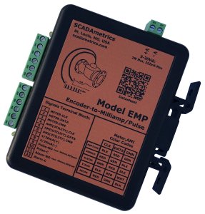
Beginning 10 Feb 2021, and thereafter, all Signalizers™ will ship with integrated “simulation mode” capability.

While in simulation mode – regardless of whether a flow meter is attached – the Signalizer will emit a constant 12 milliamps (50%) from its 4-20 milliamp terminal; and it will also emit a continuous 1 Hz pulse from its pulse terminal.
The simulation feature will allow the SCADA, telemetry, or building automation integrator to exercise and validate his controller’s I/O interface before the meter is installed or before a positive flow condition is available.
In order to activate simulation mode, both dip switches 1 and 2 should be set into the ON position. To exit simulation mode, dip switches 1 and 2 should be reset, according to the type of connected encoder meter:
| SENSUS | NEPTUNE | ELSTER | SIMULATION MODE | |
| Dip Switch #1 | OFF | ON | OFF | ON |
| Dip Switch #2 | OFF | OFF | ON | ON |
Also, every Signalizer includes a 249 Ω resistor in the shipping box. The resistor is included as another complimentary troubleshooting tool. For example, if the system integrator’s multimeter does not offer the ability to measure DC current (in order to validate the 4-20mA signal), then he may install the included resistor as a dummy load across the milliamp output terminals in order to measure DC voltage, instead (which is generally easier):
- 4mA x 249 Ω ~ 0.99 volts
- 12mA x 249 Ω ~ 2.99 volts
- 20mA x 249 Ω ~ 4.98 volts
The datasheet/manual has been modified to reflect the addition of the new simulation mode functionality….
Download PDF Datasheet / User Manual Here: TheSignalizer™
Many thanks to SCADA System Integrator Jeff Morris, Automation Manager, President – HTI Inc. (Horse Branch, KY), for the suggestion of this useful feature!
Are you interested in learning how TheSignalizer can help you more closely monitor the flow through your water meters? Give us a call! We’ll be glad to discuss the details!
