Jim ‘Slim’ Mimlitz, SCADAmetrics
Although the EtherMeter® is designed primarily as a SCADA gateway for water meters equipped with absolute encoder signals, it also provides support for dry-contact pulse output flow meters. These can include gas meters, electric meters, water meters, wastewater meters, steam meters, hot water meters, and many others.
When interfacing with mechanical pulse meters, a common challenge is handling “Contact Bounce”. For example, after a certain volume of gas flows through a meter, the meter provides a single, brief contact closure. A contact closure event might have a duration of 50 milliseconds (typical), but it may also be shorter or longer in duration, as well. The contact closure could be in the form of a “solid-state” contact (a Transistor Switch), or it could be in the form of a “mechanical” contact (a Reed Relay Switch).
When a mechanical Reed Relay switch closes, it may physically “bounce” during the make and break movements, which can be interpreted by sensitive instrumentation as multiple contact closures, instead of one, as intended. This can introduce significant over-counting errors into the monitoring system, unless properly handled through “De-Bouncing”.

In this illustration, the raw, jittery pulse signal will likely be interpreted as 8 pulses. The digitally-debounced signal, however, will be correctly interpreted as 2 pulses.
“De-Bouncing” describes the process of sensing the intended contact closure signal, while filtering out the extra, unintentional contact closures.
De-Bouncing can be implemented in hardware, by using resistors and a capacitor to form a low-pass filter. De-Bouncing can also be implemented in the EtherMeter’s software, by using high-speed sampling and signal processing algorithms.
Several years ago, SCADAmetrics introduced its first-generation, software-based De-Bounce Algorithm into the EtherMeter to provide an alternative to the resistor/capacitor hardware-based solution.
Today, SCADAmetrics is pleased to introduce its second-generation, software-based De-Bounce Algorithm. The new algorithm analyzes incoming meter pulses against the user setting “DEBOUNCE_MS”, and accumulates the pulse count according to the logic described below.
When the DEBOUNCE Algorithm is ACTIVATED, then the following logic applies:
If the CONTACT has been OPEN continuously for DEBOUNCE_MS (or more)...
AND...
The CONTACT is detected to transition to CLOSED...
THEN...
The Pulse Count will INCREMENT BY ONE.

Available De-Bounce Setting: 1ms <= DEBOUNCE_MS <= 500ms
When the DEBOUNCE Algorithm is DEACTIVATED, then the following logic applies:
If the CONTACT has been OPEN continuously for 208 usec (or more)...
AND...
The CONTACT is detected to transition to CLOSED...
THEN...
The Pulse Count will INCREMENT BY ONE.

The EtherMeter will count pulses as fast as it can detect them:
2400 pulses-per-second, maximum.
Pulse “Jitter” Simulation Rig. This Custom Device is Driven by an External Signal Generator Emitting a 1 Hz Square Wave. Output #1 is a Mechanical Contact Pulse Output. Output #2 is a Solid-State Contact Pulse Output. Used To Help Validate the SCADAmetrics EtherMeter’s Pulse Debounce Algorithm.

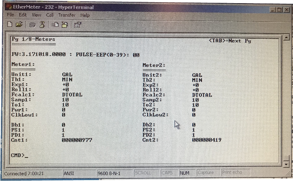
Channel 1: Mechanical Pulse with Jitter, De-Bounce Algorithm Not Activated. Channel 2: Solid-State Pulse (Clean, No Jitter). Note that the Mechanical Pulse Count (977) Is Erroneously Higher Than the Reference Solid-State Pulse Count (419) by a factor of 133%.

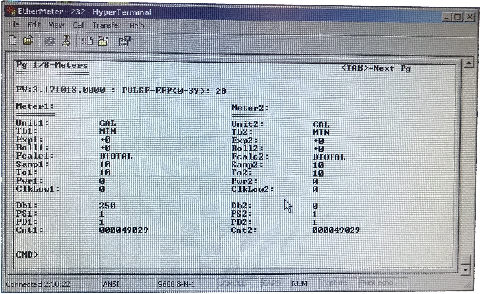
Channel 1: Mechanical Pulse Input with Jitter. De-Bounce Algorithm Activated with 250ms setting. Channel 2: Solid-State Pulse (Clean, No Jitter). Note that the Debounced Mechanical Pulse Count (49,029) Is Identical to the Reference Solid-State Pulse Count (49,029) — Thereby Validating the Effectiveness of the 2nd-Generation Digital De-Bounce Algorithm.
The Second-Generation Digital De-Bounce Feature can be enabled by setting DB1 (for meter channel 1) or DB2 (for meter channel 2) to a non-zero value. (A setting of zero de-activates the De-Bounce feature.) Valid activated settings are between 1 and 500 milliseconds. DBn should be set to approximately 1/4 of the shortest time between pulse leading edges (in milliseconds).
For simplicity, one of the following rule-of-thumb formulas could be used:
DBn (ms) = 15,000 / ( Max_Flow_GPM x Pulses_Per_Gallon )

or...

DBn (ms) = 15,000 / ( Max_Flow_CFM x Pulses_Per_Cubic_Foot )

or...

DBn (ms) = 900,000 / ( Max_Flow_CFH x Pulses_Per_Cubic_Foot )


or more generally...

DBn (ms)  =  250 / Maximum_Expected_Pulses_Per_Second


Please note that the maximum allowable DBn setting is 500 ms.
A thank you shout-out to Dennis Marsalek, MDM Global Services (Tucson, Arizona) for the many conversations and insightful advice that went into formulating this feature upgrade!
All EtherMeter firmware dated 18 Oct 2017 and later will ship with the 2nd-Generation Digital De-Bounce feature. However, the feature will be de-activated, by default. Note: If you would like to upgrade an already-purchased EtherMeter, a firmware upgrade can be factory-flashed for a nominal fee plus shipping.
Would the EtherMeter, with its Digital De-Bounced Pulse-Processing capabilities, better help integrate pulse-output flow meters into your SCADA, Telemetry, or Building Automation System? Give us a call! We’ll be glad to discuss the details!


Hi,
I am trying to connect a Gas meter ( https://www.ekmmetering.com/products/3-4-pulse-output-gas-meter-pgm-075 ) to ethermeter with:
Wires connected to 15 and 16
ethermeter config :
Meter1(Main Water): Meter2(Outside Water): Meter3(Gas):
Unit1: FT3
Tb1: MIN
Exp1: +0
Roll1: +0
Fcalc1: DTOTAL
Samp1: 10
To1: 50
Pwr1: 0
ClkLow1: 2
Db1: 0
PS1: 1
PD1: 1
Cnt1: 000000000
And the following diagnostic :
Ch:1
Extr(Unsc):000000000
dTot(Unsc):0 , dTime(x4ms):0
FLOWx1K:0
Any tips on how could be wrong please ?
When troubleshooting this problem over the phone, we determined that the meter was not functioning (not emitting pulses).
What Charif and I did — and this is a good way to test whether the EtherMeter is correctly set up to receive pulses — Use a short piece of wire to shunt across terminals 15 and 16… basically create your own dry contact pulses. When we did this, the EtherMeter’s pulse count began to increase with each contact — and therefore we were assured that the EtherMeter’s settings were correct, and that it was functioning properly.
In meters with a solid-state contact closure (not this case), the pulse-output meter wires are often polarized (+/-) and the ‘+’ should be connected to terminal.15 and the ‘-‘ should be connected to terminal.16.